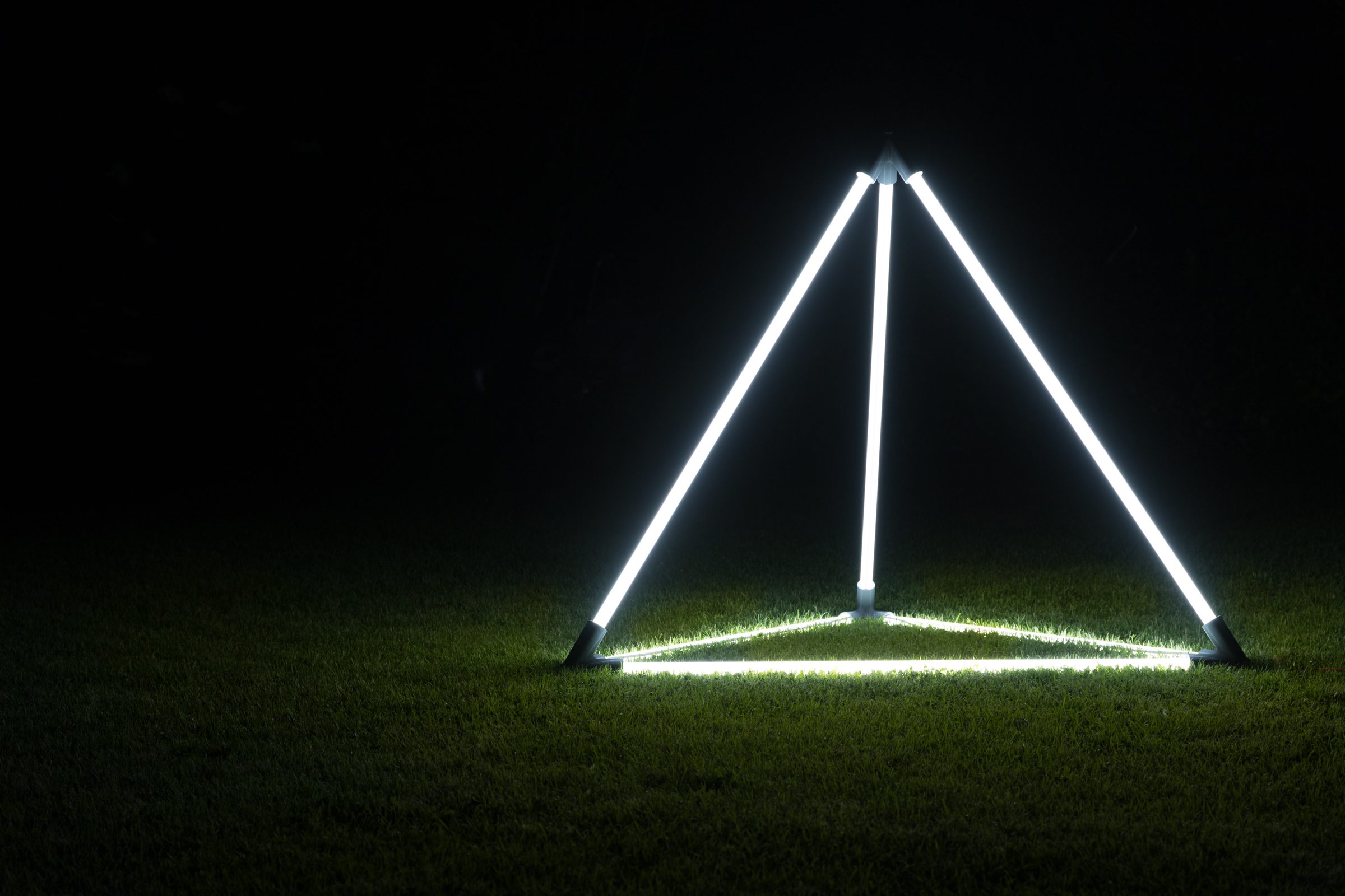
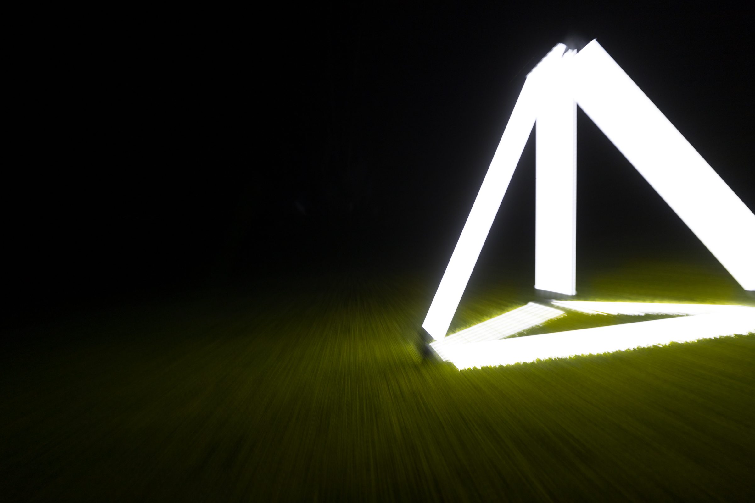
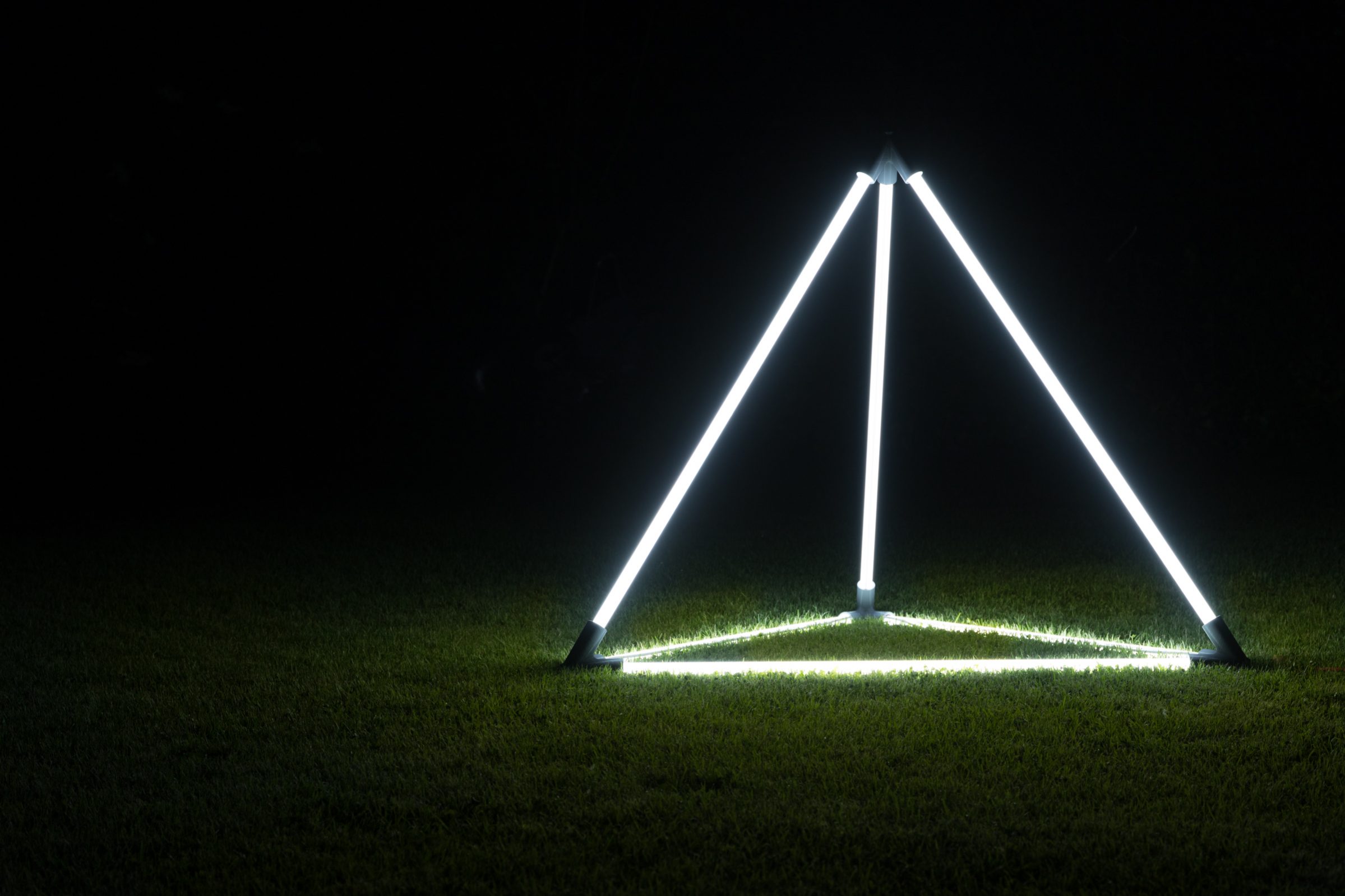
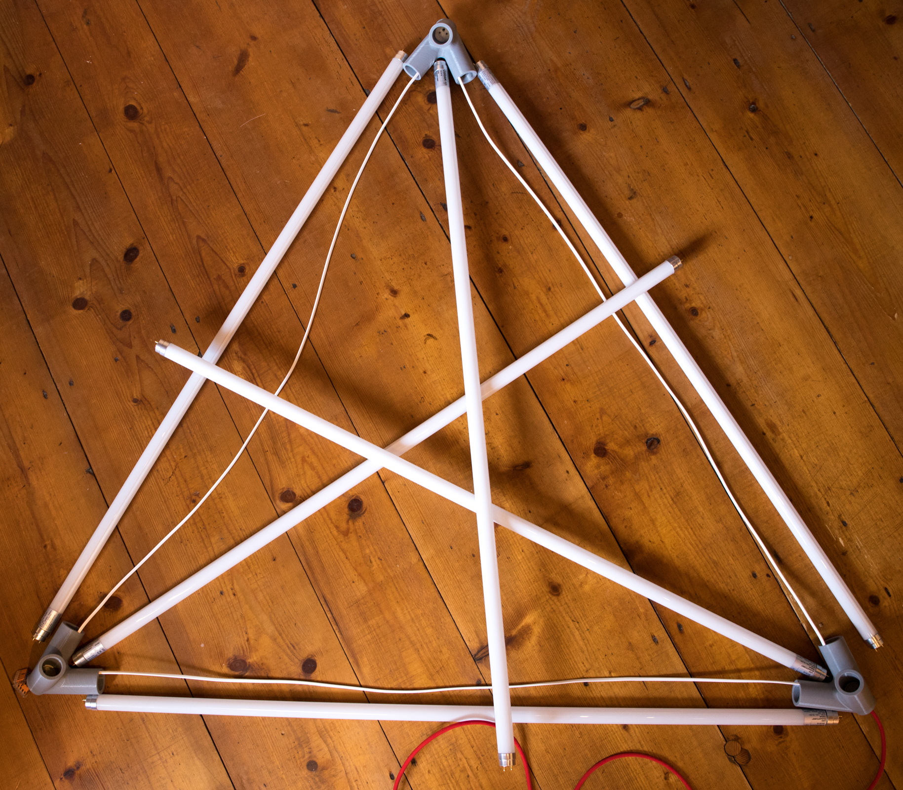
For a long time I was looking for a geometric light art installation that would look good in the garden or at events. I finally found what I was looking for at GPN19. Here was a beautiful LED tetrahedron, which I absolutely wanted to rebuild.
In Autocad Inventor I started to construct the first sketches and quickly came across the pitfalls of the construction. The angles of many levels have to fit exactly, the walls have to be strong enough for the LED tubes and there has to be space for the cabling in the corners. I learned a lot of new techniques in Inventor on the project.
It cost me many, many test prints until I finally had a well-designed object in my hand that also had special features such as fits for the lamp bases or imprinted positioning information.
You want to rebuild this thing? With pleasure.
The shopping list
| 6 pieces. Osram LED Tubes “Substitube Value T8” | 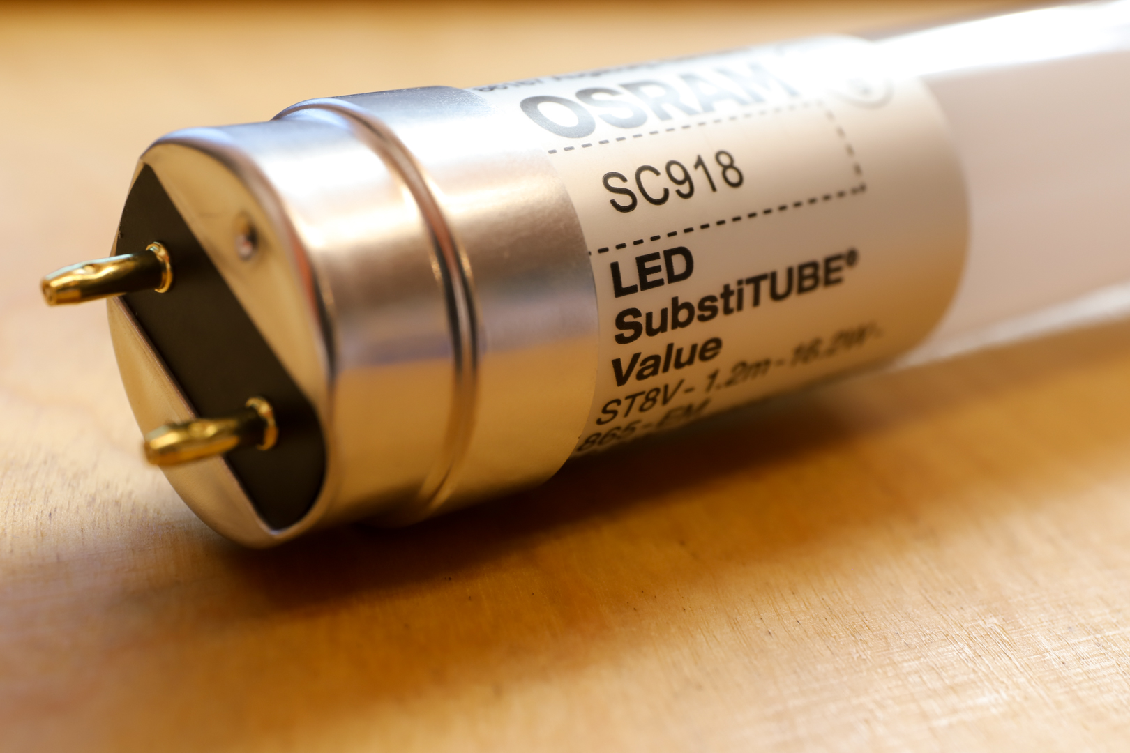 |
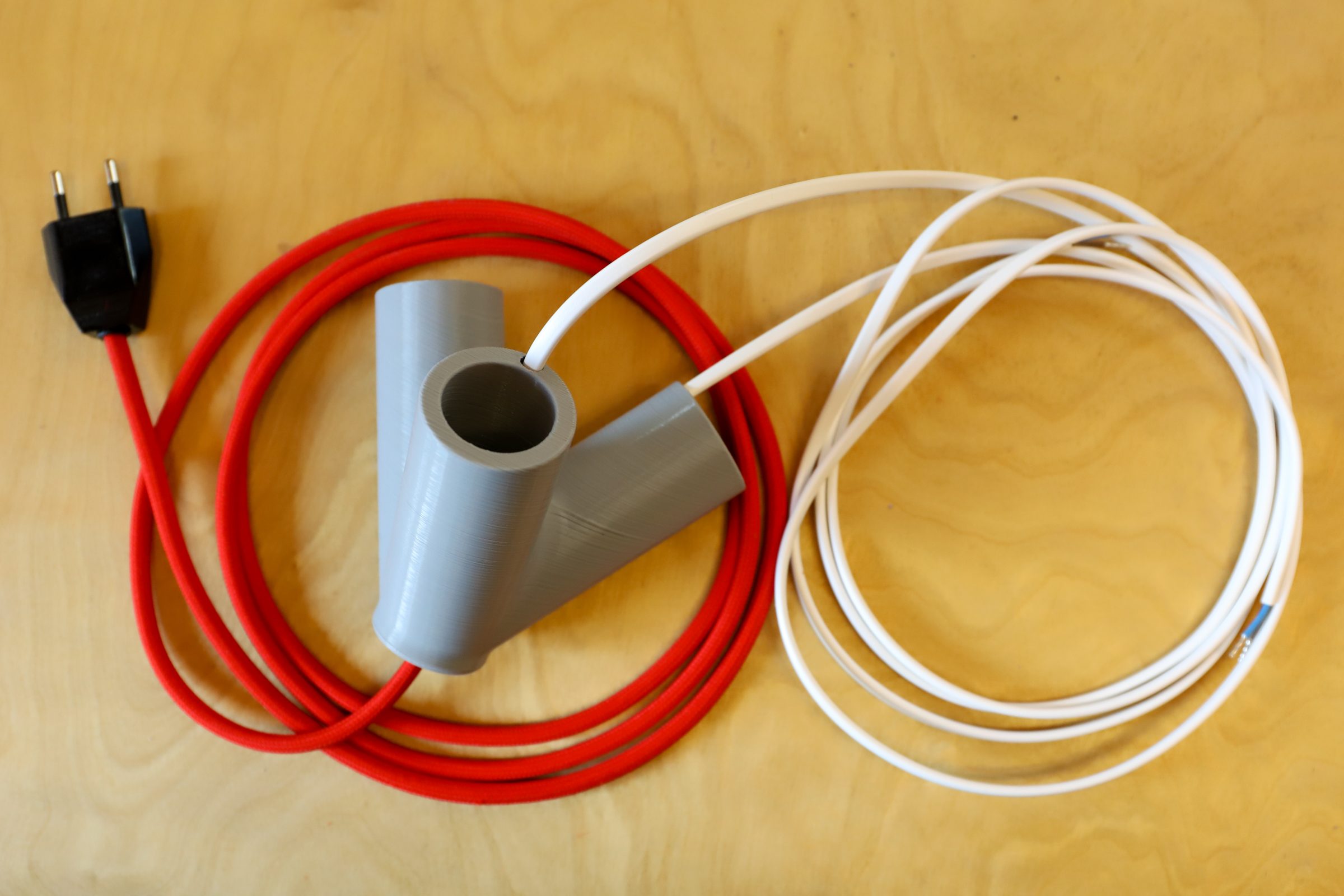
| ca. 6 Meter 2×0,75mm² Cable The exact name is “H03 VVH2-F 2×0,75” The cables are not round but oval. | 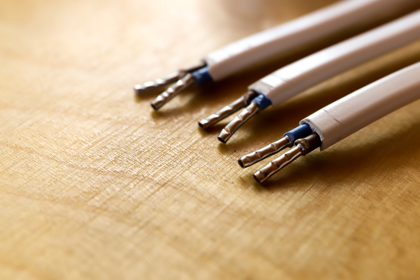 |
| 100×0,75mm wire end ferrules | 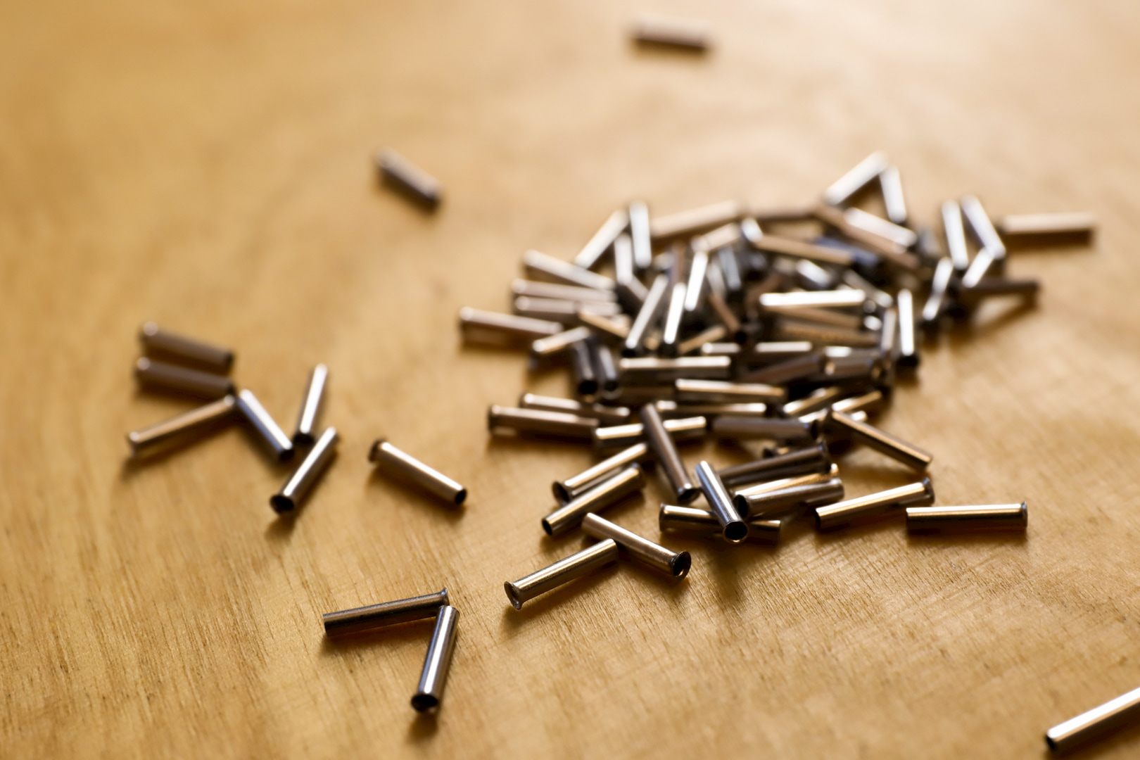 |
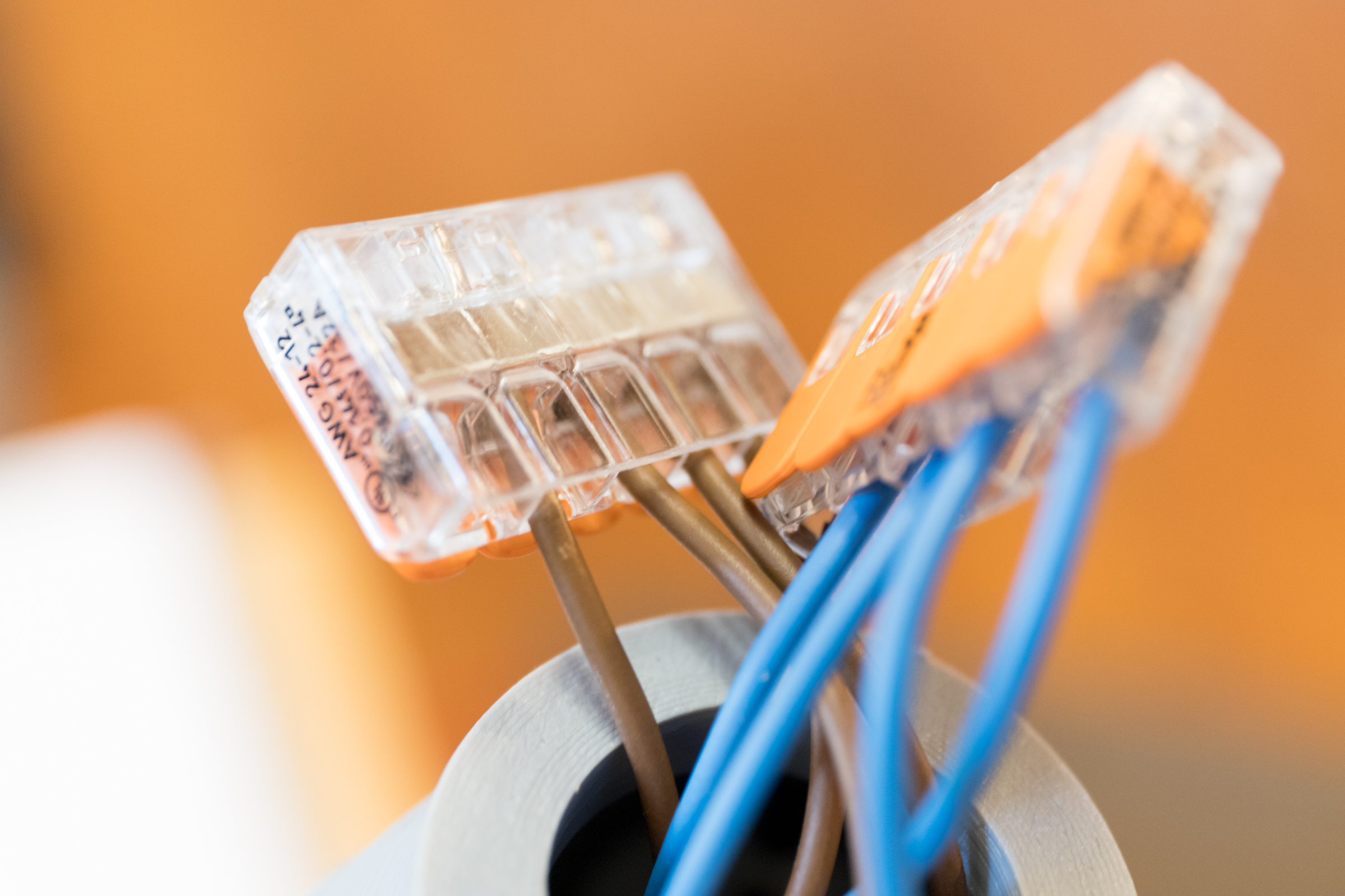
| 6 St. Wago 221 cable connectors | 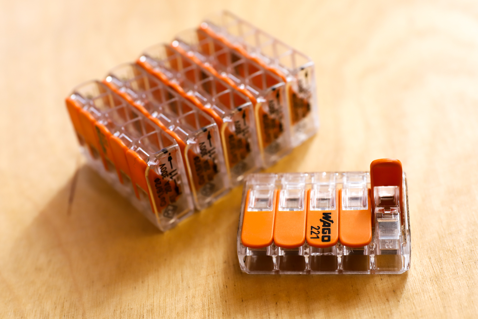 |
| 12 pieces. slip-on sockets G13 T8 | 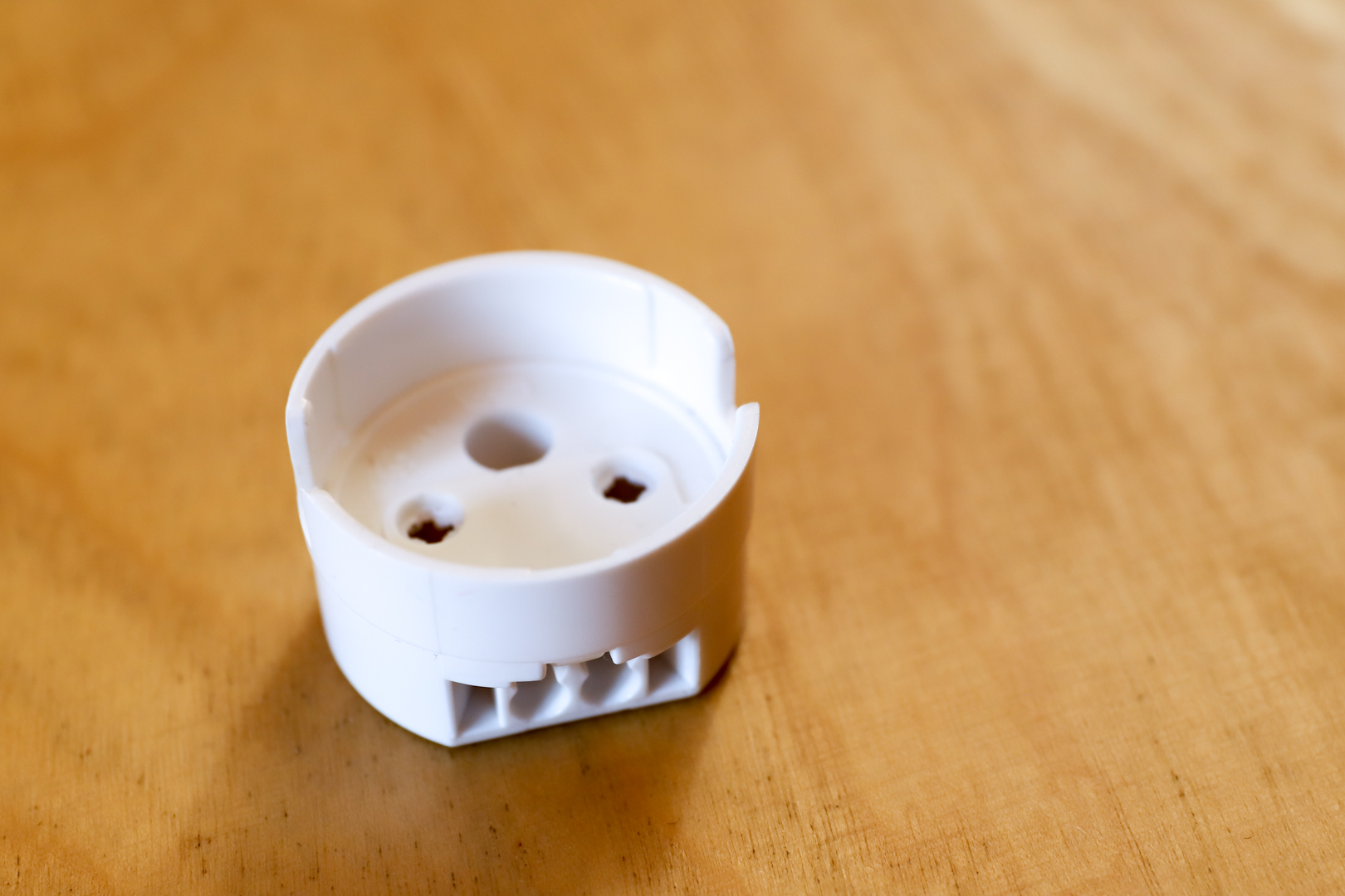 |
| ca. 400g PLA Filament | 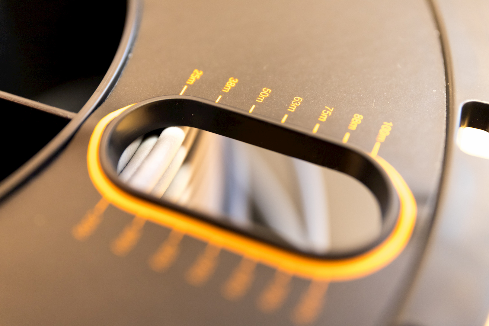 |
| 1 piece Europlug | 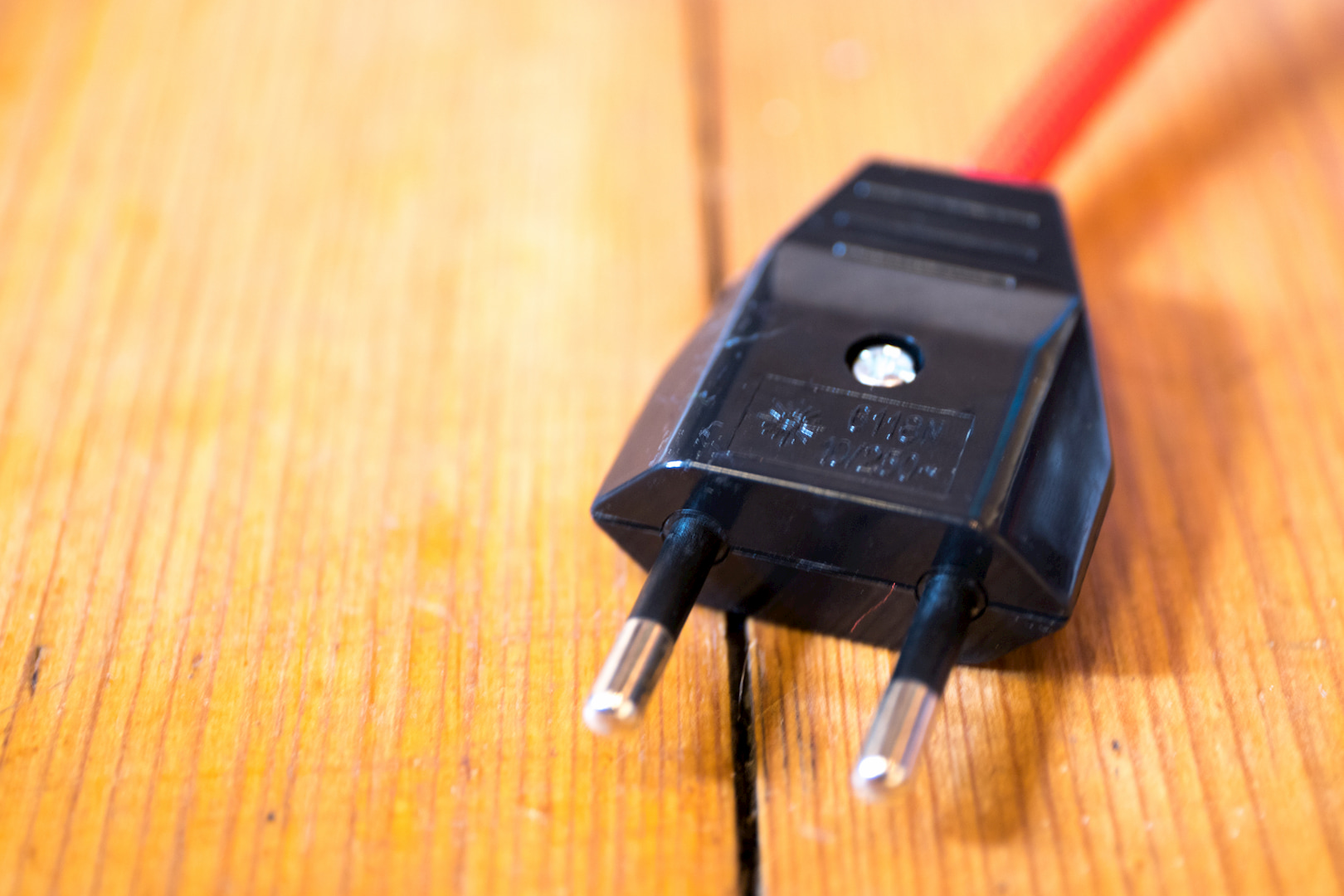 |
| 1 St. cable tie | 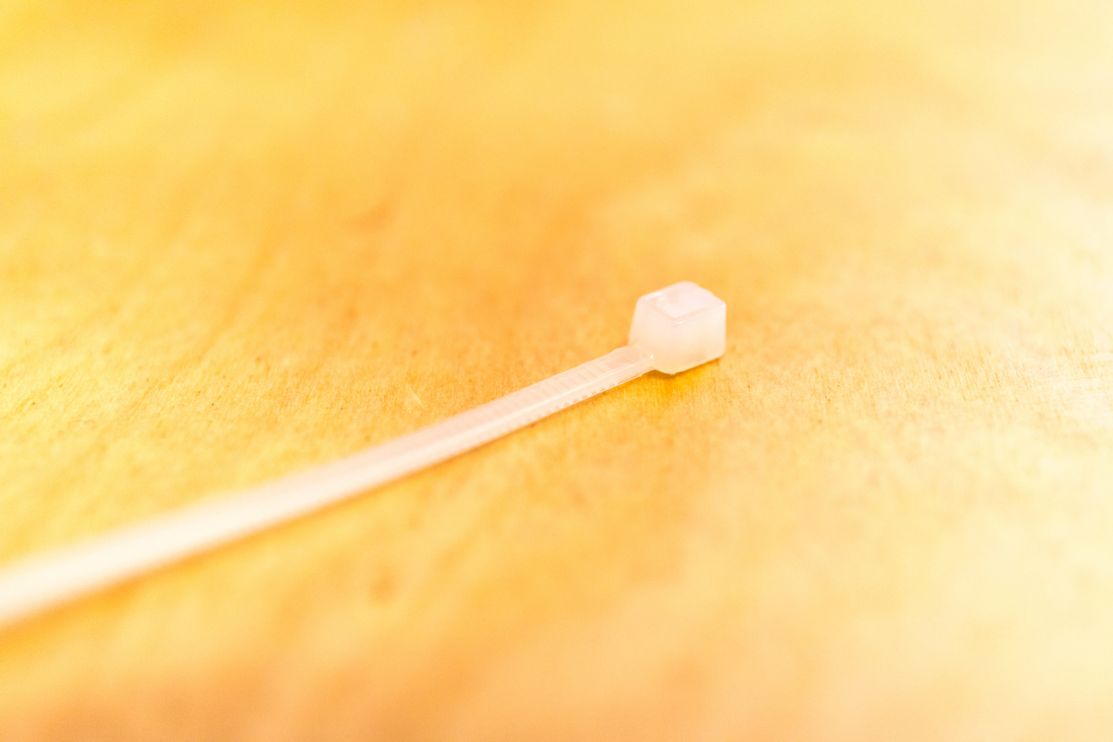 |
3D Design
The 3D print files can be found here on Thingiverse. There are also the construction files for Inventor. So you can make personal adjustments.
3D Printing
Approx. 37h printing time were it with me with a middle quality stage for the altogether 8 construction units from the 3D printer.
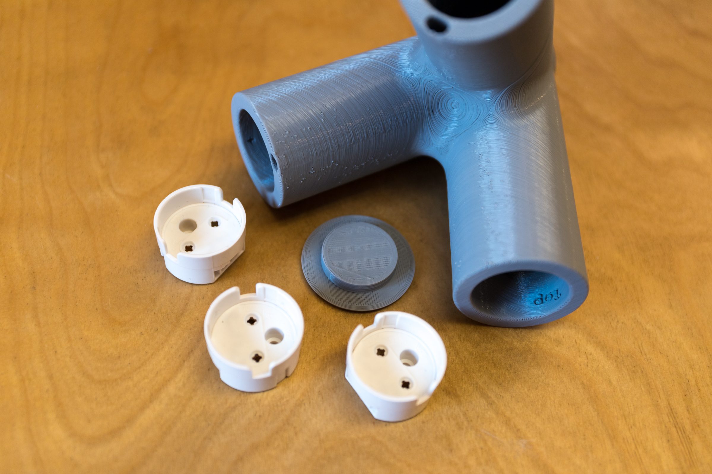
There are 3 different components. You print the corner connectors 4 times. The closed cap three times. The cover cap with the hole once.
Assembly of the “tip” corner connector
One of the four corner connectors forms the “tip” of the tetrahedron. This is not live. Only three lamp bases are inserted into it and closed with a cover without a hole. If necessary, mark it inside so that you do not confuse it with the other corner connectors. When inserting the lamp bases, you will feel a small elevation inside. This is intended to prevent the bases from falling out so easily. You can either leave it with this fuse or glue the bases lightly inside with glue.
Assembly of the “basic” corner connectors
Disclamer! You assemble components, which are later connected to 230V direct current. I myself do not provide you with any instructions which guarantee a safe assembly and operation. The manual is intended for people who can understand my steps and have electrotechnical expertise. I describe my procedure to the best of my knowledge and belief. You take full responsibility for your actions on this project!
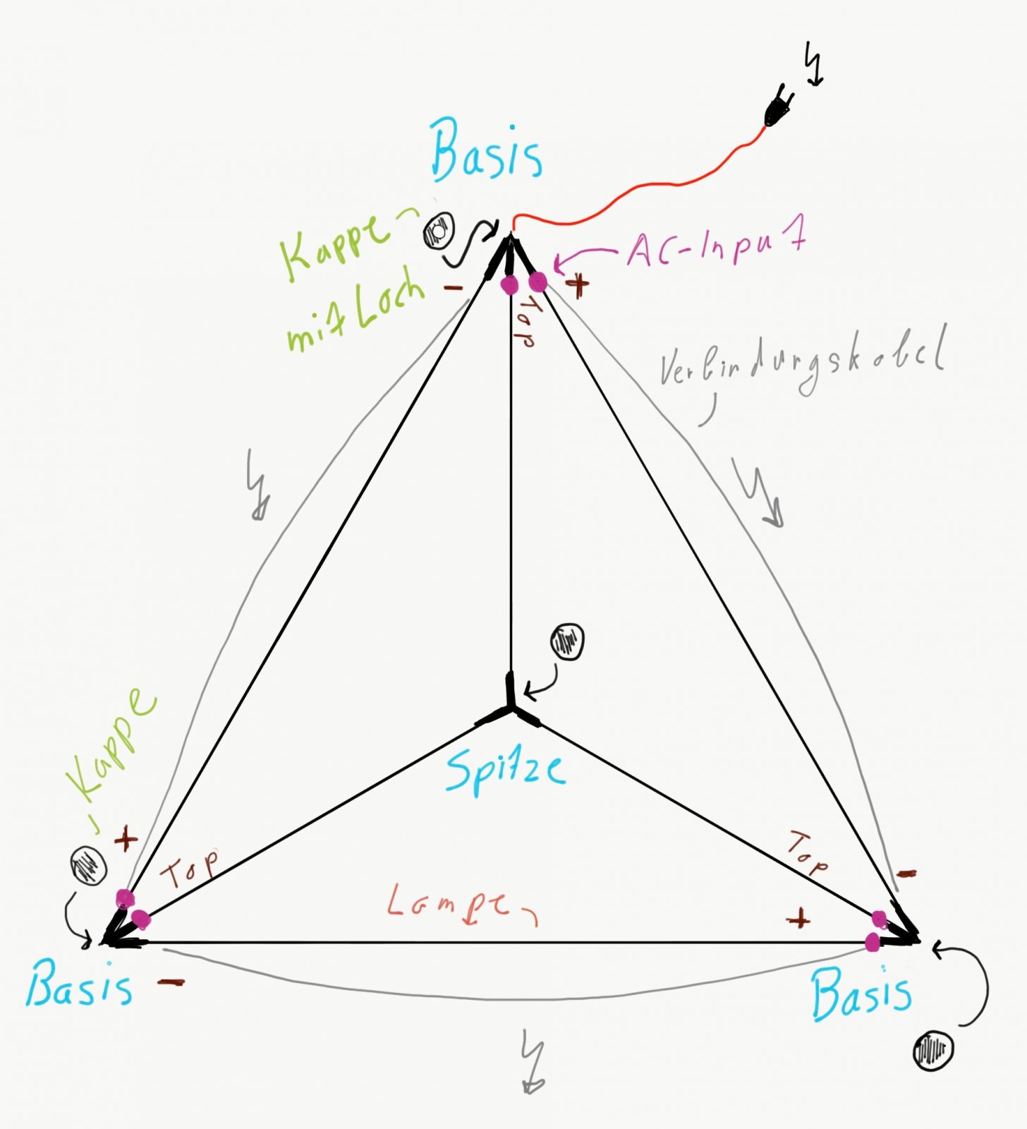
scheme 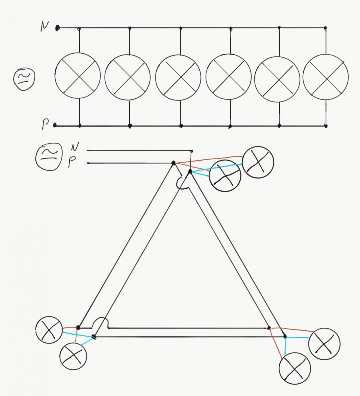
scheme
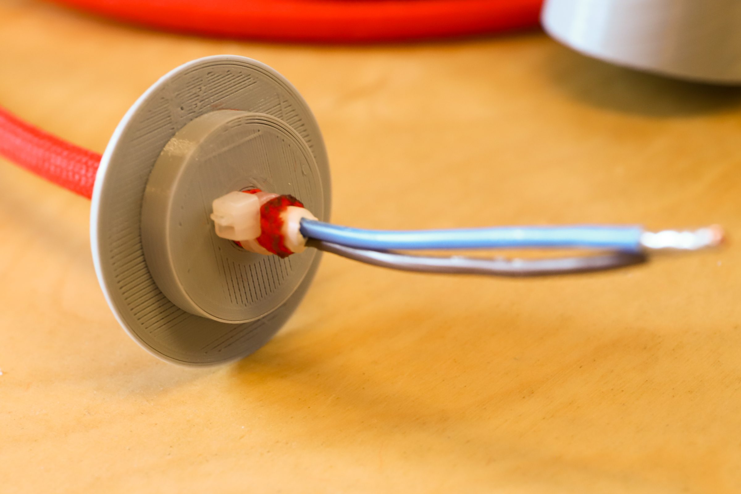
At the remaining three “base” corner connectors I connect two each! Sockets with approx. 15cm. Cables are connected. One of the sockets is NOT live. The one on the “-” side. The sockets of the “+” and “Top” side are current-carrying. The cable ends protrude from the connection hole so that we can mount them later on the cable connectors.
Now pass the two connecting cables through the two cable bushings at “+” and “-“, which supply the corner connectors with power. All cable ends are provided with ferrules.
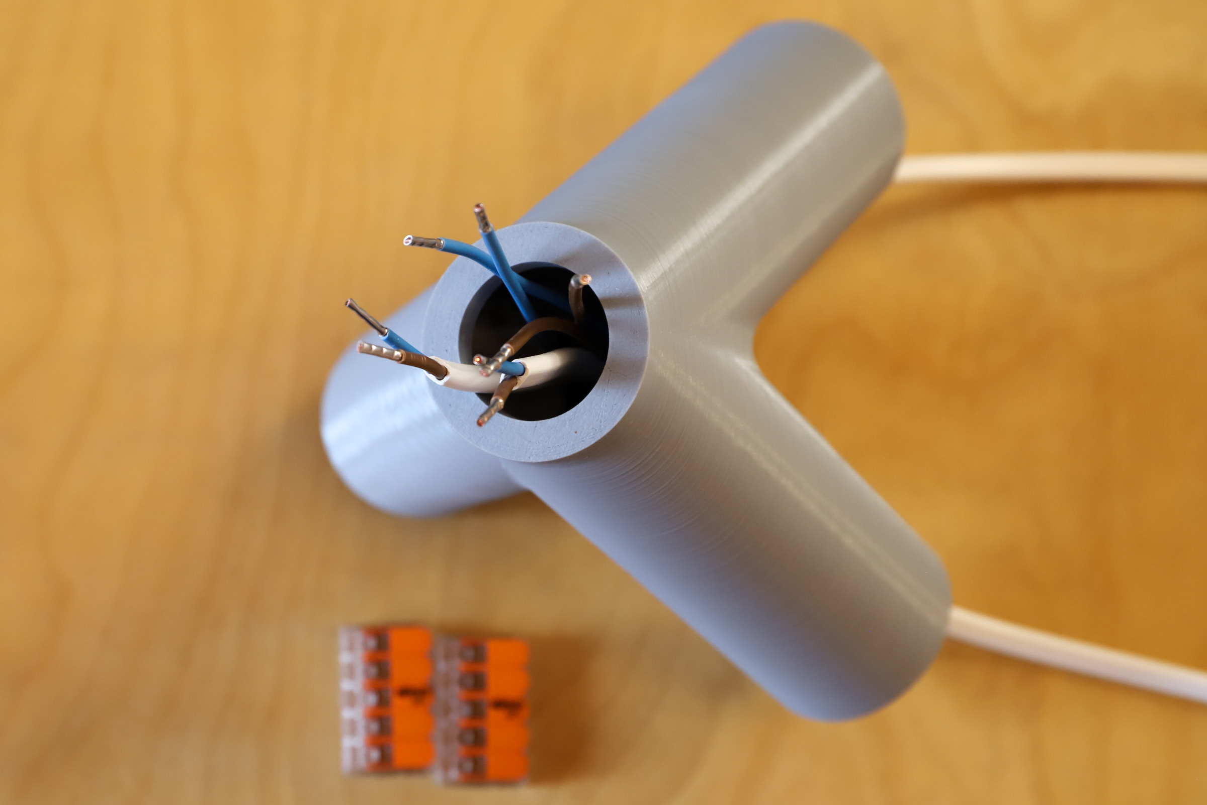
Connects the two cable colours with one terminal each.
Two of the three current-carrying corner connectors now have 4/5 of the ports occupied. If you have problems inserting the terminals into the corner connectors, it might help to shorten the cables a bit to reduce the cable clutter inside.
Corner connector with power supply
At one of the three corner connectors we mount our power supply line with the Euro plug. We lead the supply line through the cover cap and fix the cable on the inside with a cable tie so that it cannot slip out so easily. By the two cables of the supply line we occupy once all ports at the terminal.

Connection of the three corner connectors to each other
The cables connecting the corner connectors must be so long that you can just thread in the LED tubes. Theoretically it is even enough to do without the power connection from the 3rd corner connector back to the 1st corner connector. But for the sake of simplicity I close the circle.
When you socket the lamps, the connecting cables will sag. My plan is to push the white cables left and right back into the corner connectors. To avoid pulling the cable ends out of the cable clamps by mistake, you can mark the cables with a pin. You should not pull out the cables beyond this mark.

Inserting the LED tubes
CAUTION!!! My description refers to the Osram LED lamps described above. They are designed so that there is a transformer on one side. Look at the silver type plate. There is an arrow with “AC Input”. This side always belongs in the current carrying “+” or “Top” side of the corner connectors. If you plug the other side of the tube into live cables, your fuse flies out.

“-” side 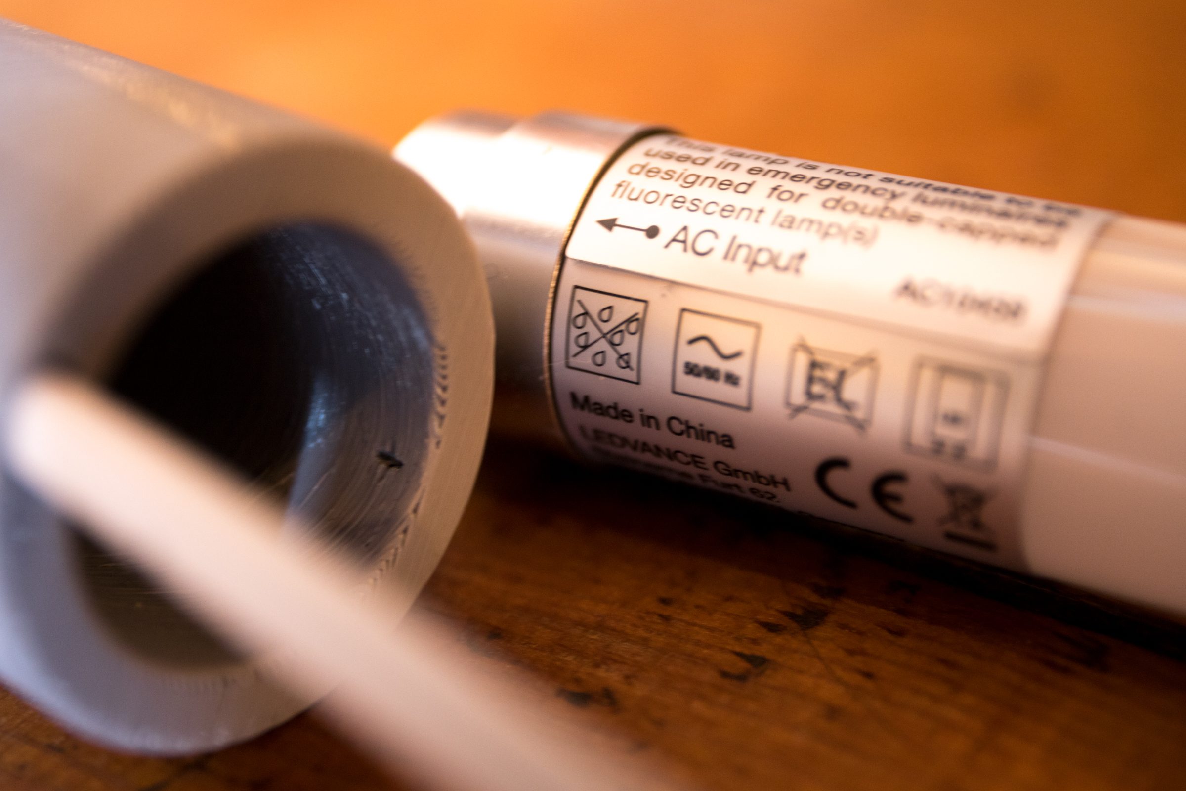
“+” side
If you use other fluorescent tubes inform you exactly if they work with the wiring as I built them.